


Utilizing CAE
The use of CAE (computer-aided engineering) is essential for optimizing and streamlining landing gear design.
CAE is used for various analyses such as the following:
We predict and examine the movement of components from a mechanical perspective, such as how to fold the leg structure so that it can be stored compactly within the aircraft, and whether it will become stuck during storage within the aircraft.
We use FEM and other methods to calculate the loads and stresses on each part when loads such as landing are applied. If there is a margin for error relative to the material allowance, we reduce the thickness to reduce weight, and then calculate the loads and stresses again in that state. By repeating this series of steps, we consider and determine the shape of the parts, etc.
(3) Landing analysis
The kinetic energy of the aircraft during landing is absorbed by air springs and hydraulic damping mechanisms installed in the landing gear.
Landing analysis is performed to predict the amount of energy absorbed and the loads on the aircraft during landing.
(4) Shimmy analysis
When a plane glides over the ground at high speed, the load transmitted from the tires can cause a large vibration known as shimmy.
Shimmy analysis takes into account the rigidity and damping factors of the leg structure to predict whether shimmy will occur and the conditions under which it will occur.
(5) Langing gear extend/retract performance analysis
The act of retracting the landing gear into the aircraft using the actuators and then extending the retracted landing gear outside the aircraft is called landing gear extension.
A landing gear retraction/extension performance analysis is conducted to predict whether the landing gear can be extended or retracted under conditions where gravity and aerodynamic loads act on the landing gear, as well as the actuator loads that will occur during the retraction/extension process.
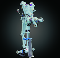
CAE application example 1: Link mechanism analysis
Link mechanisms are used in various locations during landing gear assembly, connecting components with pins so that they can rotate freely. For complex link mechanisms, such as the extend/retract link that folds the landing gear when it is stored in the aircraft body, mechanical analysis is performed using the kinematic simulation function provided by 3D CAD. In the early stages of designing the lifting link, the placement of the rotation axes between components is considered to ensure a smooth storage. As the design progresses and the detailed component shapes are determined, interference between components during lifting and lowering and gaps with the aircraft components are checked. Mechanical analysis is essential for these investigations.
Mechanism analysis example: Main landing gear extend/retract link

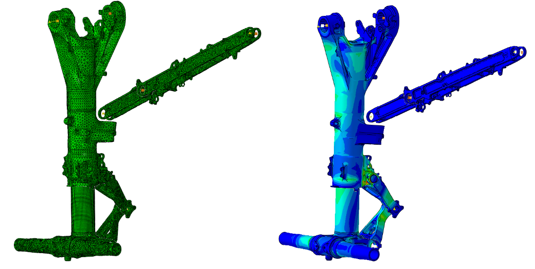
CAE Application Example 2: FEM (Finite Element Method) Analysis
Strength analysis often uses FEM analysis to calculate the load acting on components and the stress at each part.Recently, thanks to improvements in the calculation power of computers, it has become possible to perform not only analysis of a single component, but also 3D FEM analysis combining multiple components, and even analysis in which contact load is defined as the method of load transmission between those components, in a relatively short time, which helps to improve the accuracy of analysis.
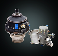
FEM analysis example 1: Stress analysis of the entire main landing gear
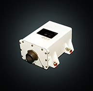
FEM analysis example 2: Stress analysis of an uplock device

Related links
Links
Contact Us
Contact Us